
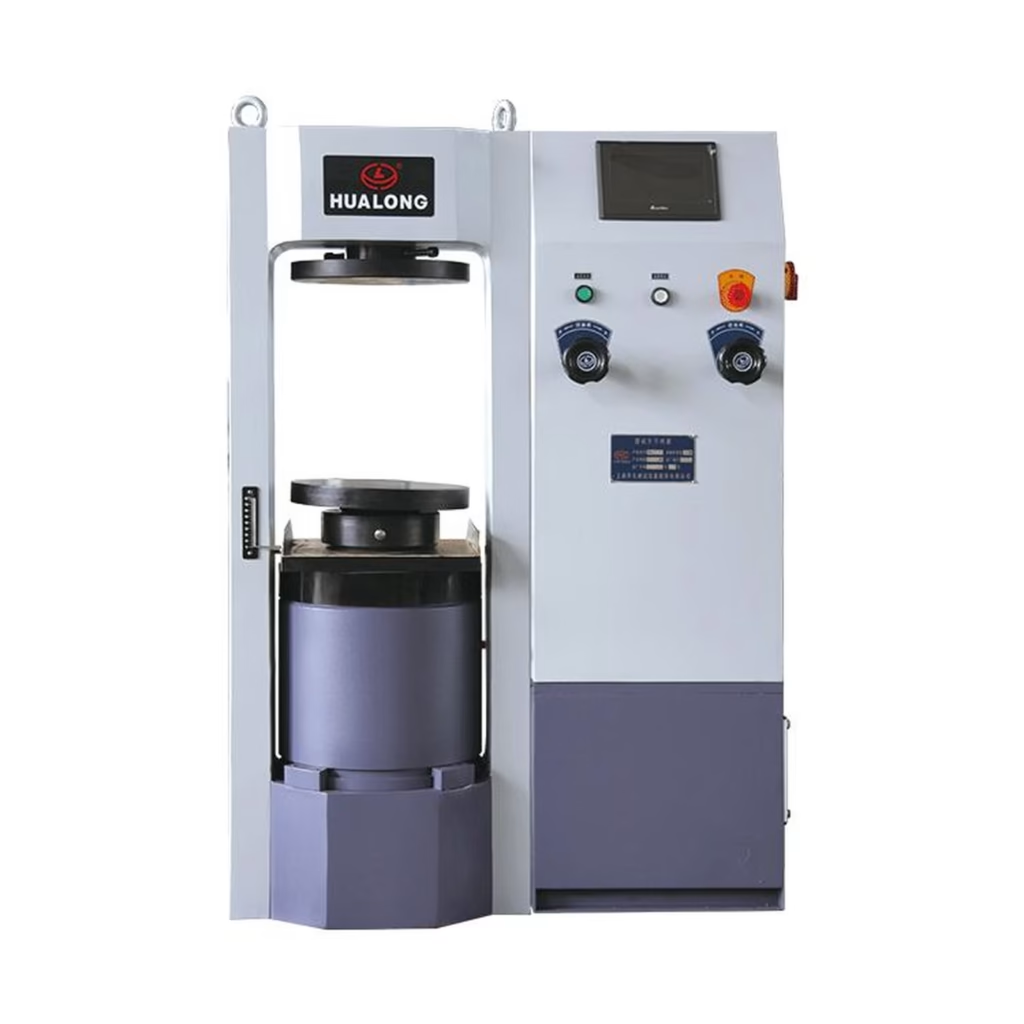
Compressive strength is the single most reported property of hardened concrete, and the test for it is the gate through which every concrete mix must pass before a structure is accepted. A standard cylinder or cube is loaded axially to failure in a compression testing machine, and the peak load divided by the cross-sectional area becomes the compressive strength in megapascals. The method is defined on both sides of the Atlantic by ASTM C39/C39M for cylindrical specimens and by EN 12390-3:2019 for cubes, cylinders and cores. This guide walks through the two methods, the specimen shapes and sizes, the curing and moisture conditions that drive the result, the loading rate rules, how to compute strength, the common failure modes an operator should recognize, and what to look for when buying a compression machine that can be verified to ASTM E4 or ISO 7500-1.
The test applies a monotonic axial load to a hardened specimen at a controlled rate until failure. The compressive strength is the maximum load recorded, divided by the cross-sectional area of the bearing face. Because concrete is a quasi-brittle material, the measured strength depends on the specimen geometry, the end conditions (how flat and parallel the loaded faces are), the moisture state at test time, and the speed at which the load is applied. The same mix poured and tested in two different curing regimes can legitimately read 15 to 20 percent apart, which is why the standards do not treat curing and capping as optional detail.
North American practice uses 150 mm diameter by 300 mm cylinders (or 100 mm by 200 mm for smaller aggregates), defined by ASTM C39 and AASHTO T22. European, British and much of Asian practice uses 150 mm cubes, with 100 mm cubes allowed for smaller aggregates, defined by EN 12390-3. A cube reads higher in compressive strength than a cylinder of the same concrete because of the stronger confinement effect from the platens on a shorter, squarer specimen; a 150 mm cube of normal-strength concrete typically reads about 20 to 25 percent higher than a 150 by 300 mm cylinder of the same batch. That gap is exactly why Eurocode 2 uses the paired notation fck,cube / fck,cyl for each strength class, so that a mix specified in one convention can be converted into the other without guessing.
Specimens are molded in rigid steel or cast-iron molds, finished, and left in the molds for 24 hours under controlled temperature before demolding. After demolding they are either stored in a fog room at 20 ± 2 °C and relative humidity above 95 percent, or immersed in lime-saturated water at 20 ± 2 °C, depending on the standard. Cylinders tested in the saturated surface-dry state immediately after removal from the curing room give a lower, more repeatable strength than specimens that have dried; cubes tested oven-dry can read several MPa higher. The standards require specimens to be tested within a short window after removal from curing, because once a specimen leaves the moist environment its strength begins to drift.
| Item | ASTM C39 (cylinder) | EN 12390-3 (cube) | EN 12390-3 (cylinder) |
|---|---|---|---|
| Standard specimen | 150 mm dia × 300 mm | 150 mm cube | 150 mm dia × 300 mm |
| Smaller specimen | 100 mm dia × 200 mm | 100 mm cube (for max aggregate ≤ 20 mm) | 100 mm dia × 200 mm |
| Curing temperature | 23 ± 2 °C, RH ≥ 95% fog room or lime water | 20 ± 2 °C, RH ≥ 95% or lime-saturated water | 20 ± 2 °C, RH ≥ 95% or lime-saturated water |
| Test age for acceptance | 28 days (often 7 days also reported) | 28 days (often 7 days also reported) | 28 days (often 7 days also reported) |
| End preparation | Cap or grind to plane within 0.05 mm | Molded faces used as-molded or ground | Cap or grind to plane within 0.05 mm |
Both standards control the loading rate tightly, because a faster load produces a higher apparent strength. ASTM C39 requires a stress rate between 0.25 and 0.70 MPa per second for cylinders. EN 12390-3 requires a stress rate between 0.6 and 1.0 MPa per second for cubes and cylinders, held constant until failure. The machine must be able to maintain that rate automatically; a manual pump that the operator adjusts by hand is the most common source of between-laboratory scatter. The specimen is centered on the lower platen, the upper platen (preferably a spherically seated one) is brought down to contact, and load is applied continuously until the needle backs off and the specimen visibly cracks. The peak load at failure is recorded.
The calculation is deliberately simple: compressive strength equals failure load divided by the cross-sectional area of the bearing face. For a 150 mm diameter cylinder the nominal area is π × 75² ≈ 17 671 mm², so a 600 kN failure load gives 600 000 / 17 671 ≈ 33.9 MPa. For a 150 mm cube the area is 150 × 150 = 22 500 mm², so the same 600 kN load gives 26.7 MPa. For cores and non-standard specimens the actual measured diameter or side length is used, not the nominal one, because a tapered or out-of-round specimen biases the result. Results from a set of three specimens are averaged, and any single result that deviates by more than about 15 percent from the average is flagged for review against the standard.
Eurocode 2 (EN 1992-1-1) labels concrete by the pair fck,cyl / fck,cube, where the first number is the characteristic 28-day cylinder strength and the second is the characteristic cube strength, both in MPa. The table below lists the common classes; the exact gap between cylinder and cube numbers follows the standard’s rounding, and a mix designed to one class must be accepted against the governing project specification, not against the table.
| Class | fck,cyl (MPa) | fck,cube (MPa) |
|---|---|---|
| C20/25 | 20 | 25 |
| C25/30 | 25 | 30 |
| C30/37 | 30 | 37 |
| C35/45 | 35 | 45 |
| C40/50 | 40 | 50 |
| C45/55 | 45 | 55 |
| C50/60 | 50 | 60 |
How a specimen breaks is diagnostic. A well-capped cylinder fails in a classic cone-and-shear pattern, with vertical cracks running from the platens inwards and a central cone of crushed concrete left standing. A cylinder that splits cleanly along the axis without a cone usually had a poor end cap or was not centered, so the result is suspect. A cube that crushes evenly across both faces is normal; a cube that fails in a single inclined shear plane suggests the loading rate was too fast or the specimen was too dry. Chattering or audible popping before peak load is normal for normal-strength concrete; explosive sudden failure is characteristic of high-strength concrete, where the machine should be fitted with a safety shroud and the operator should stand back.
Warning: high-strength concrete (above C50/60) can release stored elastic energy violently on failure. Always use a platen safety cage, keep the loading area clear, and confirm that the machine frame stiffness is appropriate for the grade being tested.
Capacity is the first decision. A 2000 kN frame covers 150 mm cubes and 150 by 300 mm cylinders for ordinary structural concrete up to about C80/95; a 3000 kN frame is the common choice for high-strength concrete and for 150 mm cores from heavy pavements. The machine should be a closed-loop servo-hydraulic or electromechanical frame that can hold a constant stress rate, not a manual pump. Platens must be hardened to at least 55 HRC, ground flat and parallel within 0.02 mm, and the upper platen should be spherically seated to self-align on uneven specimen ends. Force indication must be verifiable to ASTM E4 class A (or ISO 7500-1 Class 1), with a current calibration traceable to national standards. A machine that can automatically hold the peak load, switch between cube and cylinder modes, and export the load-time curve to software removes the largest sources of operator error. Materst supplies electro-hydraulic compression testing machines from 2000 kN to 3000 kN, together with capping kits, grinders and accessories for concrete cube and cylinder acceptance laboratories.
The compressive strength test is deceptively simple, and that simplicity is exactly where errors creep in. Curing temperature, moisture state, end preparation, loading rate and platen flatness all move the number, and a machine that cannot hold the rate or cannot be calibrated to ASTM E4 will silently produce results that fail inter-laboratory comparisons. Buy a frame sized for the strongest concrete in your program, insist on current force verification, run the specimen by the current edition of ASTM C39 or EN 12390-3, and read the failure mode as well as the number. Done that way, the compression test remains the most reliable single number a concrete laboratory can deliver.
Sources and references
- ASTM C39/C39M, Standard Test Method for Compressive Strength of Cylindrical Concrete Specimens — ASTM International
- EN 12390-3:2019, Testing hardened concrete — Part 3: Compressive strength of test specimens — iTeh Standards catalogue
- ASTM E4, Standard Practices for Force Calibration and Verification of Testing Machines — ASTM International
- ISO 7500-1:2018, Metallic materials — Calibration and verification of static uniaxial testing machines — ISO
- ISO 1920-3:2019, Testing of concrete — Part 3: Making and curing test specimens — ISO Online Browsing Platform