
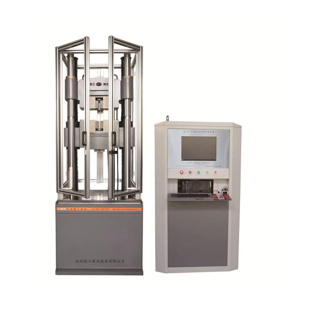
A universal testing machine (UTM) is the workhorse of any materials laboratory: a single frame that pulls, pushes, bends and shears specimens from metals, plastics, rubber, textiles, composites, concrete and geotextiles. Choosing the wrong frame is expensive — too small and it cannot test your largest specimen; too large and the load cell loses accuracy at the low end of the range. This guide walks through the decisions a lab manager has to make: frame geometry, capacity, control modes, load cell class, grips and fixtures, extensometers, software, and the calibration requirements that let the machine’s numbers be accepted by a third-party inspector. The force-measurement side of the decision is governed by ISO 7500-1 and ASTM E4, while the tensile test itself for metals is written up in ASTM E8/E8M.
A UTM consists of a rigid load frame, a driven crosshead, a force sensor (load cell), and a controller that moves the crosshead under one of three closed-loop control modes: load control, stroke (crosshead displacement) control, or position control. Attach grips for tension, compression platens for cubes, or a three-point bend fixture for flexure, and the same machine runs ASTM E8 on a steel bar one hour and a three-point bend test on a plastic beam the next. The frame itself is not universal; the set of grips, fixtures and software licenses that bolt onto it is.
Single-column (also called single-space) frames are benchtop, screw-driven machines up to about 5 kN, used for thin films, textiles, small plastics specimens, packaging and small components. They are inexpensive, fast and occupy little bench space, but they lack stiffness and are not suitable for metals or for specimens that require deep compression space. Twin-column (dual-space) frames are the default for 10 kN to 1000 kN: two columns carry a rigid crosshead, the test space sits between the upper grip and the lower table, and the frame is stiff enough to hold alignment under load. Above 600 kN most machines switch to a servo-hydraulic actuator below the table, with the frame built from four or six rods so that the tall column stays in line. The table below summarises the typical split.
| Frame type | Typical capacity | Drive | Typical applications |
|---|---|---|---|
| Single-column benchtop | 0.1 kN to 5 kN | Ball screw, servo motor | Textiles, film, packaging, small plastics, thin components |
| Twin-column screw | 5 kN to 300 kN | Two ball screws, servo motor | Plastics, rubber, aluminum profiles, rebar up to 16 mm, geotextiles |
| Twin-column servo-hydraulic | 300 kN to 1000 kN+ | Servo-controlled hydraulic actuator | Structural steel, reinforcing bar, fasteners, high-strength welds |
| Six-column servo-hydraulic | 1000 kN to 2000 kN+ | Servo-controlled hydraulic actuator | Bridge cables, large fasteners, high-strength alloy specimens |
A common mistake is buying a frame that is too large for the material, because load cells are most accurate in the middle of their range. Rule of thumb: the expected maximum force of your heaviest routine specimen should sit between 20 and 80 percent of the machine’s rated capacity. A 100 kN machine that will never see more than 30 kN is wasting its range on the soft end of the load cell, where accuracy degrades; a 50 kN machine asked to pull a 60 kN rebar specimen is both out of range and a safety hazard. List the maximum expected force for each material you test, add a 20 percent margin, and choose the smallest frame whose rating clears that list. If your program spans both 2 kN films and 500 kN rebar, plan on two frames rather than one oversized machine.
ISO 7500-1 classifies the force-measuring system of a static uniaxial testing machine into Class 0.5, Class 1 and Class 2, based on the permissible relative error and reversibility error across the verified force range. Class 0.5 keeps the error within ±0.5 percent of the indicated force; Class 1 allows ±1 percent. ASTM E4 uses an equivalent A/B/C/D grading by force indication. Routine quality control on rebar or concrete typically only needs Class 1; certified material testing in an accredited laboratory, and any test feeding a design report, should specify Class 0.5. The machine’s verification certificate must list the verified force range; a load cell verified from 10 to 100 kN on a 100 kN frame is not acceptable below 10 kN, no matter how the datasheet reads.
The crosshead speed range and the control modes the machine supports determine which standards you can actually run. Screw-driven frames typically run 0.01 to 500 mm/min; servo-hydraulic frames run from fractions of a mm/min up to several hundred mm/min at high force. Standards like ASTM E8 specify strain rates (e.g. 0.008 mm/mm/min until yield), which the machine can only hold if it supports extensometer feedback control. A machine that only runs open-loop crosshead displacement cannot satisfy strain-rate-controlled yield testing, even though it will happily run a simple tensile strength test. Check the controller supports all three modes — load, stroke and extensometer feedback — before purchase, because retrofitting closed-loop extensometer control onto an older frame is rarely economic.
The frame is only as good as the grip that holds the specimen. Wedge grips are the default for metals; flat or serrated jaw faces for thin sheet, V-notched jaws for round bar. Plastics and rubber need roller or pneumatic grips that do not crush the specimen at the grip ends. Geotextiles and woven fabrics use wide-width clamp grips that spread the force over the specimen width. Concrete specimens are not tensioned in a UTM in the simple sense; split tensile tests use a line-loading jig, and flexural tests on concrete beams use a three-point or four-point bend fixture bolted onto the lower platen. Buy the grips you will actually use next to the machine, because third-party grip compatibility is rarely plug-and-play.
| Material | Typical grip / fixture | Common test | Representative standard |
|---|---|---|---|
| Structural steel, rebar | Wedge grips, V-notched jaws | Tensile strength, yield, elongation | ASTM E8 / ISO 6892-1 |
| Plastics | Pneumatic or roller grips | Tensile modulus, strength, elongation | ISO 527 / ASTM D638 |
| Rubber | Face-serrated or roller grips | Tensile strength, modulus | ISO 37 / ASTM D412 |
| Geotextiles | Wide-width clamp grips | Tensile strength, grab test | ISO 10319 / ASTM D4632 |
| Concrete beams | Three- or four-point bend fixture on lower platen | Flexural strength | EN 12390-5 / ASTM C78 |
Crosshead displacement is not strain. The elastic stretch of the frame, the take-up of grip slack and the seating of the specimen all add to crosshead displacement, so the only defensible way to measure modulus, offset yield and elongation within gauge length is with an extensometer clipped directly onto the specimen. A digital extensometer with gauge length selectable to 50 or 100 mm, automatic return at yield, and resolution better than 1/1000 mm is the standard upgrade. Data acquisition software should capture force, displacement and extensometer channels synchronously, produce the stress-strain curve, compute Young’s modulus and offset yield automatically, and export to CSV or PDF for the test report. Software that only records peak load is acceptable for simple acceptance work, but it cannot support modulus testing.
ISO 7500-1 and ASTM E4 require an initial verification at installation, a periodic verification (typically every 12 months in an accredited laboratory, or more often if the frame is moved or repaired), and an in-process check by the operator. The in-process check is a quick force-check against a calibrated load cell or proving ring run at the beginning of each shift; the periodic verification is done by an accredited calibration laboratory with traceable reference standards. Keep the verification certificate with the machine, and record every in-process check in a logbook. If the in-process check drifts outside the class tolerance, the machine is out of service until the accredited verification is repeated.
Note: a UTM is only as good as its most recent verification. A machine purchased with a Class 0.5 certificate but never re-verified will silently drift; in an ISO/IEC 17025-accredited lab, out-of-calibration results are void and must be recalled.
- List every material and specimen you will test, with the maximum expected force for each.
- Pick the smallest frame whose rated capacity keeps the maximum force in the 20 to 80 percent band.
- Choose single-column under 5 kN, twin-column screw from 5 to 300 kN, twin-column or six-column servo-hydraulic above 300 kN.
- Specify load cell verification to ISO 7500-1 Class 1 (routine) or Class 0.5 (accredited).
- Confirm the controller runs load, stroke and extensometer-feedback closed-loop control.
- Order the grips and fixtures for the materials you actually test, not just the frame.
- Budget for an extensometer, software license and an annual ISO 7500-1 / ASTM E4 verification contract.
Materst supplies twin-column and servo-hydraulic universal testing machines from 50 kN to 1000 kN, together with wedge grips, bend fixtures, extensometers and verification services for construction-materials and metals laboratories.
A universal testing machine is a long-term capital purchase that will outlast the lab that bought it by two decades or more. The cheapest decision in year one — buying a frame too small, skipping the extensometer, accepting Class 2 force verification — becomes the most expensive problem in year three, when the lab needs to pass an accreditation audit or bid for a material-testing contract. Size the frame to the materials you actually test, specify the force class you will need in five years, and budget the grips and calibration as part of the same purchase. Done once, properly, the right UTM will run tensile, compression and flexural tests for decades without a second thought.
Sources and references
- ISO 7500-1:2018, Metallic materials — Calibration and verification of static uniaxial testing machines — ISO
- ASTM E4, Standard Practices for Force Calibration and Verification of Testing Machines — ASTM International
- ASTM E8/E8M, Standard Test Methods for Tension Testing of Metallic Materials — ASTM International
- ISO 7500-1:2018, Calibration and verification of the force-measuring system — ISO Online Browsing Platform